The hardware of The!Cart consists of two layers. The physical hardware includes the PCB carrying the chips and the logic implemented in the CPLD (Complex Programmable Logic Device). While the physical hardware can only be changed by soldering, the CPLD logic can be updated via the JTAG interface of the Xilinx CPLD chip.
Disclaimer: This update process is for experts. Verify all connections very carefully. Connecting the wrong pin to the JTAG connector can completely destroy the CPLD!
The following section describes how to update the CPLD Logic with iMPACT from ISE 10.1 and a Xilinx Platform USB Cable.
This documentation assumes that you have a Windows XP or Windows 7 PC. Older versions of the ISE suite may not yet support the required "XC95144XL" chip in The!Cart. Likewise, newer versions of Windows or the ISE suite may no longer support the chip or the USB cable. To update the CPLD logic of the with iMPACT from ISE 10.1 and a Xilinx USB Cable, follow these steps:
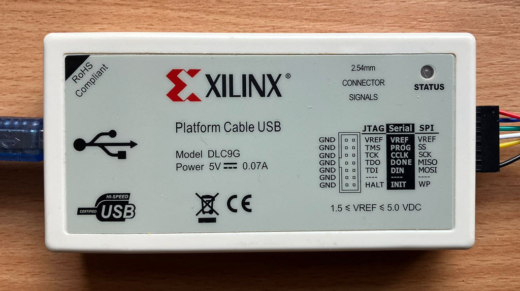
- The assumption is that you have a "Xilinx Platform Cable USB" or similar.
- Download "ISE Design Suite - 10.1" from https://www.xilinx.com/downloadNav/vivado-design-tools/archive-ise.html.
Use the Full Product Installation (6.2 GB). You will need to register at AMD to perform the download.
Download the latest CPLD software from https://www.horus.com/~hias/thecart/logic/.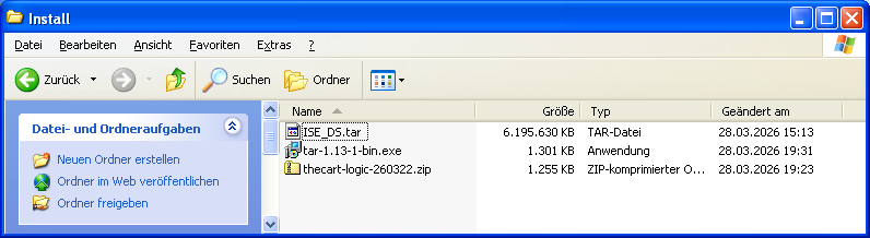
- Because Windows XP cannot uncompress ".tar" files by default, you will have to install tar.exe from https://sourceforge.net/projects/gnuwin32/files/tar/.
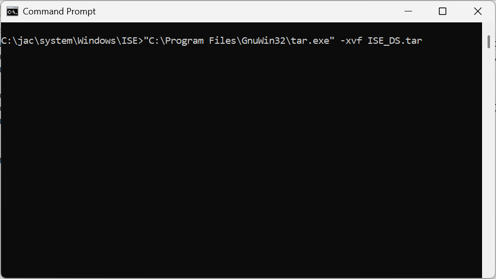
- Uncompress the "ISE_DS.tar" file by running "<tar installation foder>\tar.exe -xvf ISE_DS.tar" from the command shell in the folder of the ".tar" file. As a result, you get an "ISE_DS" folder with about the same size as the ".tar" file.
- Uncompress the CPLD software from the ZIP archive file by using the Explorer context menu.
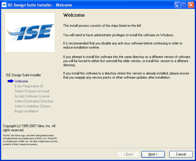
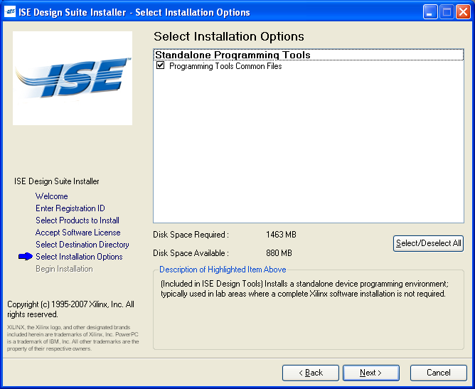
- Run the "setup.exe" from the "ISE_DS" folder as administrator. Press "Next."
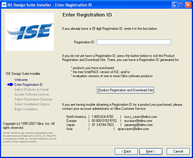
- Press "Next" without entering a registration ID.
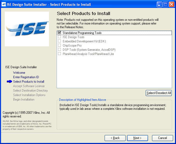
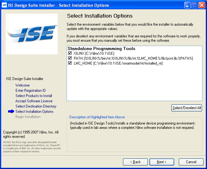
- Without the registration ID, only the Standalone Programming Tools are installed. Press "Next".
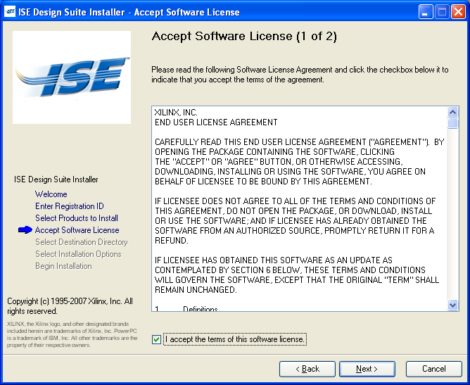
- Accept the license terms and press "Next".

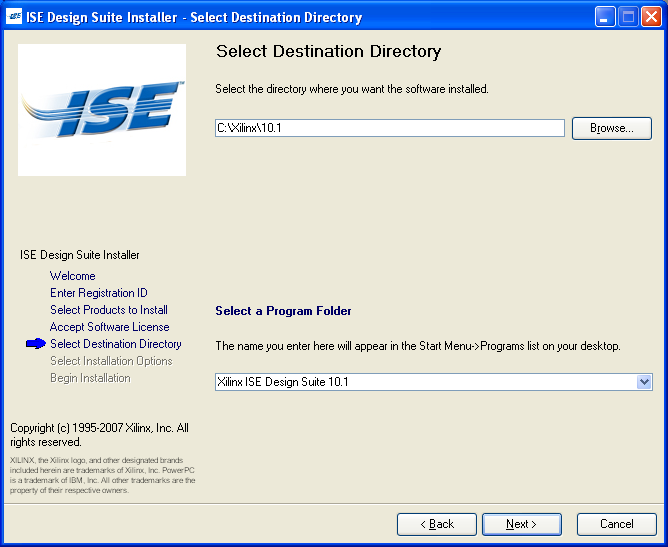
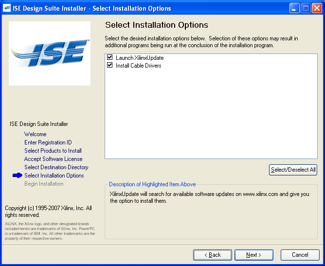
- Press "Next" for all these steps.
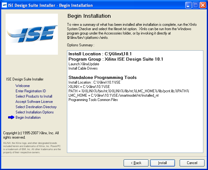
- Press "Install".
- Plug the Xilinx USB Cable into your PC. Three USB drivers and devices will be automatically installed.
- Power your Atari computer off.
- Plug your "The!Cart" into your Atari computer. Be careful to insert it with the Xilinx chip facing down/away from you.
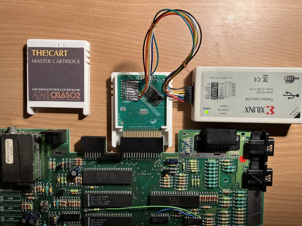
- Connect the Xilinx USB Cable to the JTAG connector on "The!Cart" as shown in the following picture.
Make sure you are looking at the top of the PCB, where a single chip is soldered diagonally.
You can use a connector strip with an 8-pin, plug it into the 8 holes, and hold it during programming for 30 seconds.
If you prefer soldering, you can also solder a permanent connector, but be careful with the length and angle; otherwise, the shell cannot be closed.
PCB Pin Counting from the Top Programmer Output 1 TCK 2 GND 3 TMS 4 Not connected 5 Not connected 6 TDI 7 TDO 8 VCC
The shell download also includes a Brother P-Touch label file to print adhesive labels for the PCB with the JTAG pin assignments.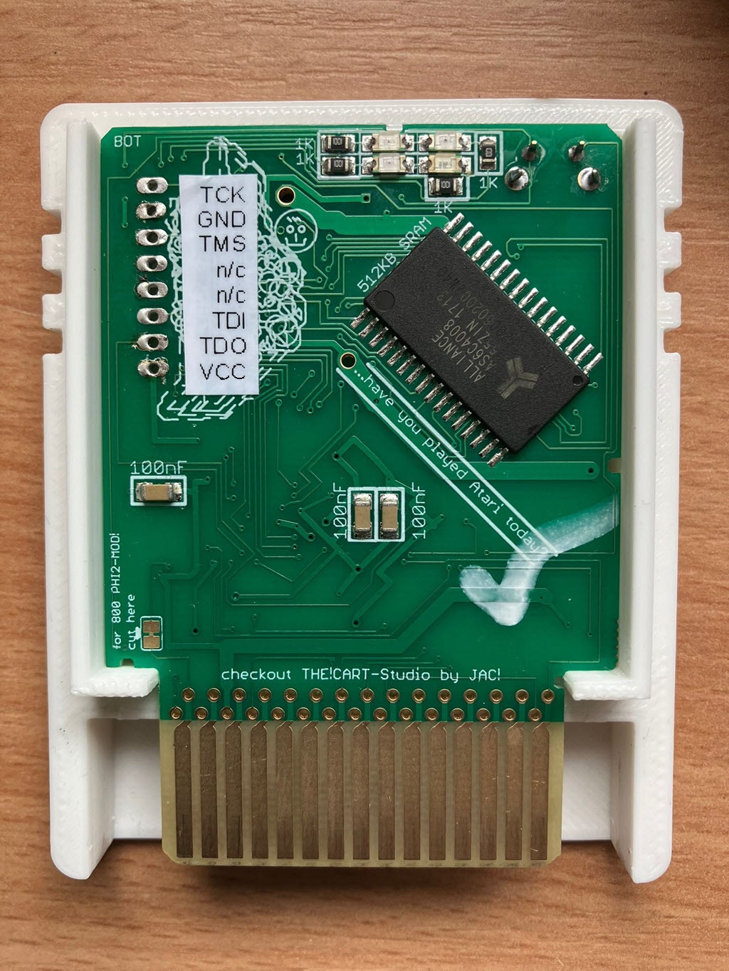
- Power on your Atari computer. The programmer's status LED should be green.
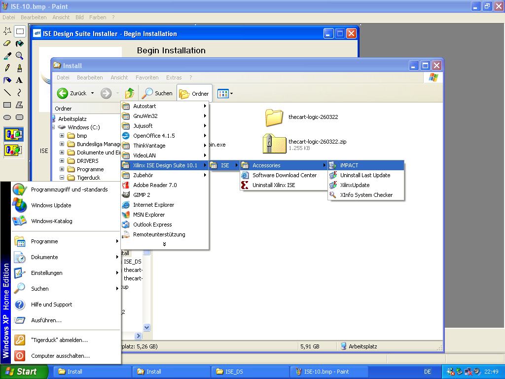
- After the installation is complete, start the program.
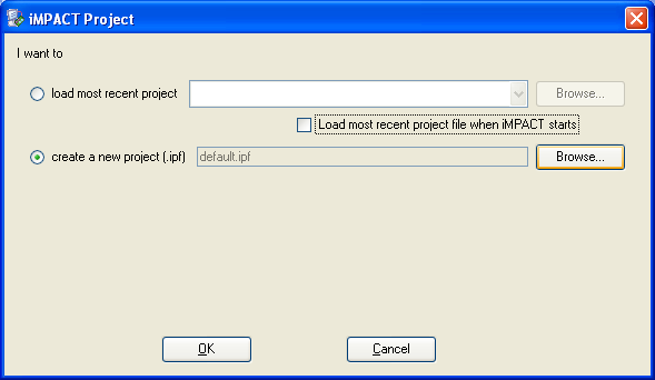
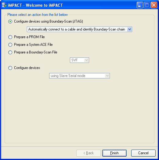
- Create a new project.
- Select "Configure devices using Boundary Scan (JTAG).
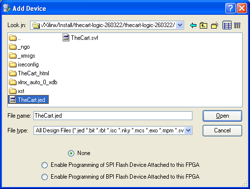
- Click "Add Device" in the menu and select "TheCart.jed" from the "thecart-logic" folder.
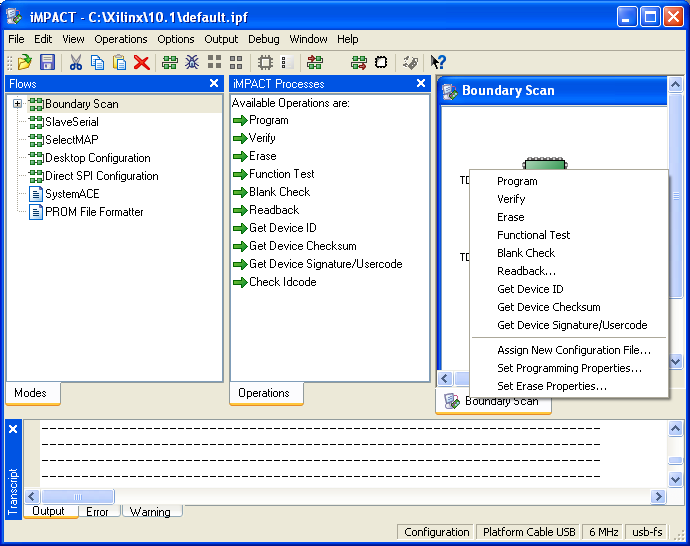
- Right-click on the device and select "Program".
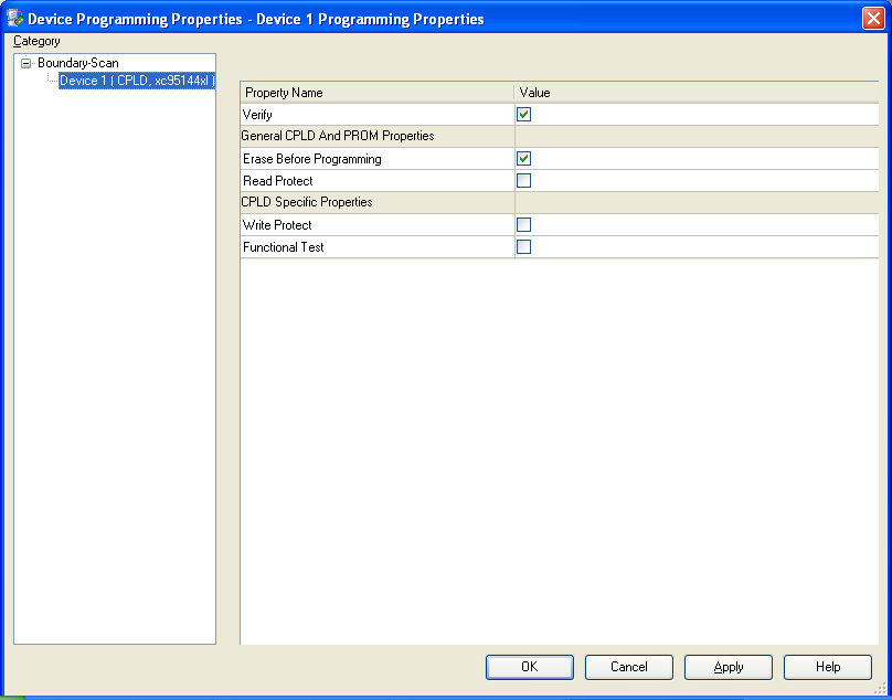
- Press "OK".
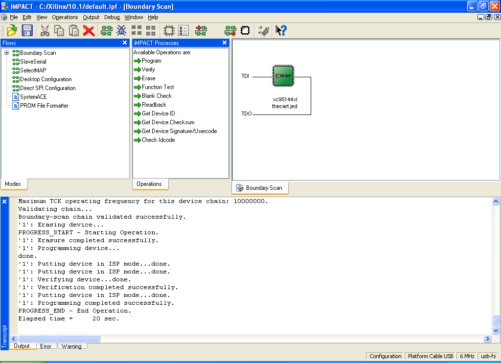
- You will see a success message in the output log.
- Power off your Atari computer and unplug the Xilinx USB Cable. The CPLD logic for "The!Cart" is now updated.